What we offer
We help to ensure the reliability and safety of your product, equipment or plant assets with our world-class service in non-destructive testing (NDT), material testing
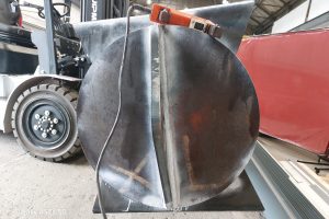
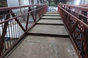
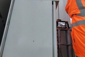
Visual Inspection (VI)
Visual inspection is the most basic form of NDT. It involves a thorough visual examination of the surface of a material or structure to detect any visible defects, such as cracks, corrosion, or weld discontinuities. Visual inspection is often the first step in an NDT process.
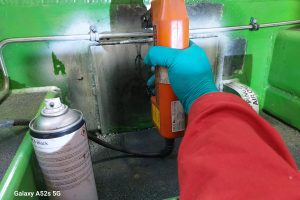
Dye Penetrant Inspection (DPI)
Dye Penetrant Testing involves applying a liquid penetrant to the surface of a material. The penetrant seeps into surface-breaking defects, and after excess penetrant is removed, a developer is applied to make the defects visible. LPT is particularly effective for detecting small cracks, porosity, and other surface discontinuities.
ADVANTAGES
• Portable (on-site and in-house).
• Relatively simple method.
• Sensitive.
• Relatively simple method.
• Sensitive.
WHAT DEFECTS/INDICATIONS CAN IT DETECT?
• Surface breaking defects.
• Toe cracks.
• Surface porosity.
• Crater cracks.
• Toe cracks.
• Surface porosity.
• Crater cracks.
LIMITATIONS
• Uses a flammable liquid.
• Power may be needed.
• Temperature dependent.
• A clean surface is required before inspection.
• Power may be needed.
• Temperature dependent.
• A clean surface is required before inspection.
ALTERNATIVE INSPECTION METHODS
• Magnetic Particle Inspection (MPI) Note: Only on ferromagnetic materials.
• Eddy Current Inspection (EC).
• Eddy Current Inspection (EC).
DPI is used to detect surface braking defects only and is generally used on.
Non-ferromagnetic materials but can still be used on ferromagnetic materials if required.
Magnetic Particle Inspection (MPI)
Magnetic Particle Testing is used for detecting surface and near-surface defects in ferromagnetic materials. A magnetic field is applied to the material, and magnetic particles are applied to the surface. The particles accumulate at areas of magnetic field distortion, highlighting defects such as cracks.
MPI is used to detect surface breaking, or very near surface, defects on ferromagnetic materials only.
MPI involves applying a magnetic field to a material and then applying magnetic particles to the surface. Discontinuities in the material cause the particles to accumulate, indicating the presence of a flaw.
Key advantages of Magnetic Particle Inspection
• Sensitivity to Surface Discontinuities: MPI is highly sensitive to surface and near-surface defects, making it effective for detecting cracks and other discontinuities that may affect the integrity of a component.
• Quick and Cost-Effective: The inspection process is relatively quick, and the equipment is often portable, making it a cost-effective method for routine inspections.
• Suitability for Field Inspections: MPI can be performed in the field, making it suitable for inspecting structures and components in their operational environment.
However, it's important to note that MPI has limitations. It is primarily effective for ferromagnetic materials and is limited to detecting discontinuities near the surface. Additionally, it may not be suitable for components with complex geometries or irregular shapes.
ADVANTAGES
• Portable (on-site and in-house).
• Relatively simple method.
• Sensitive.
• Quick instant results.
• Sub-surface defects detection possible (approximately 1mm-2mm).
• Relatively simple method.
• Sensitive.
• Quick instant results.
• Sub-surface defects detection possible (approximately 1mm-2mm).
WHAT DEFECTS/INDICATIONS CAN IT DETECT?
• Surface breaking defects.
• Toe cracks.
• Surface porosity.
• Crater cracks.
• Toe cracks.
• Surface porosity.
• Crater cracks.
COMMONLY USED TO TEST.
• Weldings.
• Castings.
• Shafts.
• Castings.
• Shafts.
LIMITATIONS
• Uses a flammable liquid.
• Power may be needed.
• Temperature dependent.
• A clean surface is required before inspection.
• Power may be needed.
• Temperature dependent.
• A clean surface is required before inspection.
ALTERNATIVE INSPECTION METHODS
• Dye Penetrant Inspection (DPI).
• Eddy Current Inspection (EC).
• Eddy Current Inspection (EC).
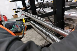
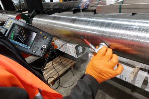
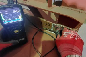
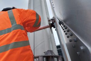
Ultrasonic Inspection (UT)
Ultrasonic Testing utilises high-frequency sound waves to inspect the internal structure of a material. Ultrasonic waves are sent into the material, and reflections are analysed to identify flaws. UT is versatile and can be used for thickness measurements, flaw detection, and characterization of defects.
UT is best used to detect internal planar defects and verify material thickness. UT can be used on most materials.
ADVANTAGES
• Portable (on-site and in-house).
• High penetrating capability.
•Quick instant results.
•Thickness gauging can be carried out through surface paint.
• High penetrating capability.
•Quick instant results.
•Thickness gauging can be carried out through surface paint.


WHAT DEFECTS/INDICATIONS CAN IT DETECT?
• Corrosion or thinning (known as ‘thickness gauging’).
• Inclusion/laminations. Internal planar defects (such as lack of fusion).
• Cracks and voids.
• Inclusion/laminations. Internal planar defects (such as lack of fusion).
• Cracks and voids.
COMMONLY USED TO TEST
• Storage tanks.
• Forgings & castings.
• Pressure vessels.
• Welds in high pressure environments.
• Structural steel welds.
• Forgings & castings.
• Pressure vessels.
• Welds in high pressure environments.
• Structural steel welds.
LIMITATIONS
• Uses a flammable liquid.
• Power may be needed.
• Temperature dependent.
• A clean surface is required before inspection.
• Power may be needed.
• Temperature dependent.
• A clean surface is required before inspection.
ALTERNATIVE INSPECTION METHODS
• Radiography (RT).
• Phased Array Ultrasonic Testing (PAUT).
• Phased Array Ultrasonic Testing (PAUT).
Phased Array Ultrasonic Testing (PAUT)
PAUT uses an array of ultrasonic transducers to create and manipulate ultrasonic beams. This allows for enhanced control over the direction and focus of the beams, providing detailed imaging of internal structures and the ability to inspect complex geometries.
Phased Array Ultrasonic Testing (PAUT) is an advanced Ultrasonic method which gives the client a permanent record of the inspection results. It is a very versatile method and can be utilized across a broad range of components.
UT is best used to detect internal planar defects and verify material thickness. UT can be used on most materials.
ADVANTAGES
• Large volume of data collected. Portable. Good for monitoring purposes. Good for complex geometries. Permanent record of data/inspection results. Reduced scanning times in comparison to manual ultrasonics.
WHAT DEFECTS/INDICATIONS CAN IT DETECT?
• Corrosion or thinning (known as ‘thickness gauging’).
• Inclusion/laminations.
• Internal planar defects (such as lack of fusion).
• Cracks and voids.
• Inclusion/laminations.
• Internal planar defects (such as lack of fusion).
• Cracks and voids.
COMMONLY USED TO TEST
• Storage tanks.
• Pipe work.
• Pressure vessels.
• Forgings/castings. environments.
• Small metal components.
• Pipe work.
• Pressure vessels.
• Forgings/castings. environments.
• Small metal components.
LIMITATIONS
• Will not detect surface breaking defects. Material thickness (a minimum material thickness may be required when inspecting welds). More reliant on a clean/smooth material surface
ALTERNATIVE INSPECTION METHODS
• Radiography (RT).
• Ultrasonic Testing (UT).
• Ultrasonic Testing (UT).
Time of Flight Diffraction (ToFD)
TOFD is an ultrasonic testing technique that measures diffracted waves to accurately size and locate defects. It is particularly effective for detecting and characterizing cracks, weld defects, and other discontinuities.
Time of Flight Diffraction (ToFD) uses an ultrasonic pulse to find and detect flaws in welds along with weld overlays and the heat affected zones of other components.
Time of Flight Diffraction (ToFD) uses an ultrasonic pulse to find and detect flaws in welds along with weld overlays and the heat affected zones of other components.
ADVANTAGES
• TOFD defect detection does not depend on the defect orientation, in contrast to the pulse.
Planar defects and cracks, which are not perpendicular to the measured surface can be detected.
When Engineering Critical Assessment (ECA) is applied, only the relevant defect must be cut, thereby preventing needless repairs which could harm the integrity of the weld.
Results are immediately available with a permanent record.
Defect height can be exactly determined.
WHAT DEFECTS/INDICATIONS CAN IT DETECT?
• Corrosion or thinning (known as ‘thickness gauging’).
• Inclusion/laminations.
• Internal planar defects (such as lack of fusion).
• Cracks and voids.
• Inclusion/laminations.
• Internal planar defects (such as lack of fusion).
• Cracks and voids.
COMMONLY USED TO TEST
• Storage tanks.
• Pressure vessels.
• Clad materials. environments.
• Piping.
• Structural steel.
• Pressure vessels.
• Clad materials. environments.
• Piping.
• Structural steel.
LIMITATIONS
• More reliant on a clean/smooth surface.
• Material thickness (A minimum material thickness may be required when inspecting welds).
• The weld must be feasibly accessible from both sides.
• There is a dead zone for defect detection under the surface.
• Material thickness (A minimum material thickness may be required when inspecting welds).
• The weld must be feasibly accessible from both sides.
• There is a dead zone for defect detection under the surface.
ALTERNATIVE INSPECTION METHODS
• Radiography (RT).
• Ultrasonic Testing (UT).
• Phased Array Ultrasonic Testing (PAUT)
• Ultrasonic Testing (UT).
• Phased Array Ultrasonic Testing (PAUT)
Radiography (RT)
Radiographic Testing involves the use of X-rays or gamma rays to inspect the internal structure of a material. It is effective for detecting internal defects such as voids, inclusions, and cracks.RT is commonly used in industries like aerospace and welding.
RT involves the use of X-rays or gamma rays to inspect the internal structure of a material. It is often used to detect flaws such as cracks, voids, or inclusions.
RADIOGRAPHY (RT) GAMMA
Radiography (RT) is the most used NDT method in detecting volumetric, internal defects in welds and castings. There are two Radiography methods that can be used, X-Ray & Gamma radiography. Both methods can be used in-house in purpose-built radiography bays and on site.
ADVANTAGES
• No surface preparations required.
• Permanent record in the form of a radiograph.
• Can be used on most materials.
• No minimum material thickness required.
• No power required. Is more suitable for complex geometries incomparison to X-Ray.
• Portable for onsite operations in comparison to X-Ray. Ability to detect small defects.
• Permanent record in the form of a radiograph.
• Can be used on most materials.
• No minimum material thickness required.
• No power required. Is more suitable for complex geometries incomparison to X-Ray.
• Portable for onsite operations in comparison to X-Ray. Ability to detect small defects.
WHAT DEFECTS/INDICATIONS CAN IT DETECT?
• Internal planar defects (such as lack of fusion).
• Cracks
• Volumetric defects (such as slag and porosity).
• Voids and solid inclusions.
• Corrosion or thinning (profile method.
• Cracks
• Volumetric defects (such as slag and porosity).
• Voids and solid inclusions.
• Corrosion or thinning (profile method.
COMMONLY USED TO TEST
• Storage tanks.
• Pipe work.
• Pressure vessels.
• Small metal components.
• Forgings/castings.
• Welds
• Pipe work.
• Pressure vessels.
• Small metal components.
• Forgings/castings.
• Welds
LIMITATIONS
• Can only be used in controlled areas (areas need to be cordoned off with restricted access.
• Can affect other site operations being carried out (for example, other trades cannot be in close proximity).
• Can affect other site operations being carried out (for example, other trades cannot be in close proximity).
ALTERNATIVE INSPECTION METHODS
• Radiography (RT).
• Phased Array (PA).
• RADIOGRAPHY (RT) X-RAY
• Phased Array (PA).
• RADIOGRAPHY (RT) X-RAY
Eddy Current Testing (ECT)
Eddy Current Testing uses electromagnetic induction to detect and characterize surface and near-surface defects. It is commonly applied to conductive materials and is used in the aerospace industry, among others, for inspecting components like aircraft engine parts.
ADVANTAGES
• Good for complex geometries.
• Portable.
• Can be used on painted surfaces.
• Advanced EC sets can provide permanent records of inspection data.
• Instant results.
• Relatively little surface preparation needed.
• Portable.
• Can be used on painted surfaces.
• Advanced EC sets can provide permanent records of inspection data.
• Instant results.
• Relatively little surface preparation needed.
WHAT DEFECTS/INDICATIONS CAN IT DETECT?
• Pitting.
• Shallow and tight surface fatigue cracks.
• Stress corrosion cracks in pipes and tubes.
• Shallow and tight surface fatigue cracks.
• Stress corrosion cracks in pipes and tubes.
COMMONLY USED TO TEST
• Aircraft fuselage and wings.
• Pipes and tubes.
• Heat Exchangers.
• Welds.
• Pipes and tubes.
• Heat Exchangers.
• Welds.
LIMITATIONS
• ECT can only be used on conducive materials.
•Any defects found need to be backed up by another inspection technique, for example, MPI.
•Any defects found need to be backed up by another inspection technique, for example, MPI.
ALTERNATIVE INSPECTION METHODS
• Magnetic Particle Inspection (MPI).
• Dye Penetrant Inspection (DPI)
• Dye Penetrant Inspection (DPI)
Alternating Current Field Measurement (ACFM)
ACFM stands for Alternating Current Field Measurement. It is a non-destructive testing (NDT) technique that is primarily used for the inspection of ferrous materials, such as steel, to detect and size surface-breaking cracks and other defects.
key features and aspects of Alternating Current Field Measurement (ACFM)
Eddy Currents
When the alternating magnetic field encounters a surface-breaking crack or defect, eddy currents are induced in the material. The presence of the crack disrupts the flow of eddy currents, creating a measurable change in the magnetic field.
Applications
ACFM is commonly used in industries such as oil and gas, maritime, and aerospace for inspecting structures, pipelines, and other components where the detection and sizing of surface cracks are critical for safety and integrity.
Portable Systems
ACFM systems are often portable, allowing for on-site inspections. This portability is valuable for inspecting components in their operational environment without the need for extensive disassembly.
Detection and Measurement
A receiver in the ACFM system detects the changes in the magnetic field caused by the presence of defects. By analysing these changes, the system can identify the location and size of the defects.
ADVANTAGES
ACFM has several advantages, including the ability to inspect surfaces with coatings, the provision of quantitative data on defect size, and the capacity to detect defects in various orientations.
• Quantitative Analysis.
One of the advantages of ACFM is its ability to provide quantitative data about the size of surface cracks. This quantitative analysis makes it a valuable tool for assessing the severity of defects and determining whether they meet acceptable standards.
• Surface Inspection.
ACFM is particularly useful for inspecting surfaces that may be coated or covered with paint, rust, or other materials. It can effectively detect and size defects even when they are not visible to the naked eye.
Complement to Other NDT Techniques
ACFM is often used in conjunction with other NDT techniques, such as ultrasonic testing or magnetic particle inspection, to provide a more comprehensive assessment of the material's condition.
ACFM is a valuable NDT technique for the detection and sizing of surface-breaking cracks and defects in ferrous materials. Its ability to provide quantitative data and its suitability for inspecting coated surfaces make it a versatile tool in various industries.
Positive Material Identification (PMI).
PMI stands for Positive Material Identification. It is a non-destructive testing (NDT) method used to determine the composition of materials, particularly in metal alloys. The goal of PMI is to verify that the material used in a component or structure matches the specified or required composition. This is crucial in industries where the use of specific materials with certain alloy compositions is critical for the performance and integrity of the product.
PMI is a fast and Non-Destructive method of verifying the chemical composition of metals and alloys. PMI is portable and can be carried out in-house or on clients’ sites.
PMI is a fast and Non-Destructive method of verifying the chemical composition of metals and alloys. PMI is portable and can be carried out in-house or on clients’ sites.
key aspects of Positive Material Identification (PMI)
• Methodology:
PMI methods involve the use of various techniques to analyse the elemental composition of a material. Common methods include X-ray fluorescence (XRF), optical emission spectrometry (OES), and laser-induced breakdown spectroscopy (LIB
Applications
PMI is commonly used in industries such as petrochemical, aerospace, construction, and manufacturing, where the correct alloy composition is crucial for safety, quality, and compliance with industry standards.
Quality Control and Assurance:
PMI is an essential tool for quality control and assurance. It helps ensure that the materials used in construction, fabrication, or manufacturing meet the specified requirements and standards.
On-Site and Laboratory Testing:
PMI can be performed on-site using portable handheld devices or in a laboratory setting with more sophisticated equipment. On-site testing is often preferred for its convenience, especially in situations where components are large or immobile.
Verification of Welds:
PMI is frequently used to verify the composition of welds, ensuring that the welding material matches the base material and that the weld meets the required specifications.
X-ray Fluorescence (XRF):
XRF is a widely used PMI technique. It involves irradiating a sample with X-rays, which cause the atoms in the material to emit characteristic X-ray fluorescence. By measuring the energy and intensity of these emitted X-rays, the elemental composition of the material can be determined.
Optical Emission Spectrometry (OES):
OES involves applying electrical energy to the material, causing it to emit light. The emitted light is then analysed to determine the elemental composition. OES is particularly effective for analysing metals and alloys.
Laser-Induced Breakdown Spectroscopy (LIBS):
LIBS uses a laser to ablate a small amount of material from the surface of the sample. The resulting plasma emits light, and the analysis of this light provides information about the elemental composition of the material.
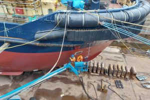
Corrosion Mapping
Corrosion Mapping is best used to map and monitor internal corrosion and can be used with automated scanners, manually, or using a Phased Array (PA) Hydro form method.
ADVANTAGES
• Large volume of data collected.
• Good for monitoring purposes.
• Inspection can be carried out through surface paint.
• No scaffolding required when using automated scanners (on ferromagnetic material).
WHAT DEFECTS/INDICATIONS CAN IT DETECT?
• Corrosion or thinning.
• Inclusions/laminations.
• Cracks.
• Inclusions/laminations.
• Cracks.
COMMONLY USED TO TEST
• Storage tanks.
• Pressure vessels.
• Pipe work (more commonly used on large diameter pipe work).
• Pressure vessels.
• Pipe work (more commonly used on large diameter pipe work).
LIMITATIONS
• Surface condition needs to be clean/ smooth.
• Automated scanner can only be used on ferromagnetic materials.
• Can be difficult to use on complex geometries.
• Automated scanner can only be used on ferromagnetic materials.
• Can be difficult to use on complex geometries.
ALTERNATIVE INSPECTION METHODS
• Phased Array (PA) (Hydro form method).
• Radiography (RT) (Profile method).
• Radiography (RT) (Profile method).
IRIS Inspection
IRIS is an ultrasonic inspection method used for the Non-Destructive Testing of tubes and pipes. The IRIS probe is inserted into the tube or pipe and flooded with water, the probe is pulled out slowly and the data is displayed & recorded.
IRIS stands for Internal Rotary Inspection System, and it is a non-destructive testing (NDT) technique used primarily for inspecting the integrity of tubes, pipes, and other cylindrical structures. IRIS inspection is particularly valuable in industries such as oil and gas, power generation, and petrochemicals, where the condition of tubing is critical for safety and efficiency.
Here are key points about IRIS inspection:
Principal:
The IRIS inspection method relies on the use of ultrasound to assess the thickness and integrity of the tube or pipe wall. It is especially effective for detecting and sizing defects such as corrosion, erosion, pitting, and wall thinning.
Applications:
IRIS inspection is commonly used in various industries where tubular structures are prevalent. It is frequently employed for inspecting heat exchanger tubes, boiler tubes, steam generator tubes, and other critical components in industrial plants.
Challenges:
While IRIS is a powerful technique, it may face challenges in inspecting tubes with complex geometries or tight bends. Additionally, the inspection speed can be relatively slow compared to some other methods.
In summary, IRIS inspection is a valuable NDT technique for assessing the condition of internal surfaces in tubular structures. It plays a crucial role in ensuring the integrity and safety of components in industries where tubing is a critical part of various processes.
Advantages:
Some advantages of IRIS inspection include its ability to provide detailed images of internal features, its accuracy in measuring wall thickness, and its sensitivity to various types of defects. It is also capable of inspecting non-ferrous materials.
Equipment:
The IRIS inspection system typically consists of a probe with an ultrasound transducer mounted on the end of a rotating shaft. The probe is inserted into the tube or pipe, and the shaft is rotated as the inspection progresses.
Ultrasound Emission:
The ultrasound transducer emits pulses of ultrasonic waves into the material. These waves travel through the material and are reflected back to the transducer when they encounter changes in material properties, such as defects or the tube wall.
Reflection Analysis:
By analysing the time taken for the ultrasound waves to travel through the material and the amplitude of the reflections received, the IRIS system creates a cross-sectional image of the tube or pipe. This image provides detailed information about the condition of the internal surface.
Capabilities:
IRIS inspection is capable of producing high-resolution images and accurately measuring wall thickness. It is particularly well-suited for detecting and characterizing defects in thin-walled tubing, and it can provide valuable information about the extent of corrosion or other forms of deterioration.
Hardness Testing
Material hardness testing determines a materials strength by measuring its resistance to indentation.
Hardness testing is a non-destructive testing (NDT) method used to determine the resistance of a material to deformation, wear, or scratching. It provides an indication of the material's hardness, which is often related to its mechanical properties. Various methods are employed for hardness testing, each suited to specific types of materials and applications.
Hardness testing is a non-destructive testing (NDT) method used to determine the resistance of a material to deformation, wear, or scratching. It provides an indication of the material's hardness, which is often related to its mechanical properties. Various methods are employed for hardness testing, each suited to specific types of materials and applications.
Some common hardness testing methods include:
Rockwell Hardness Testing:
Rockwell hardness testing involves applying a major load and then measuring the depth of penetration of an indenter into the material. The Rockwell hardness number is determined based on the difference in depth before and after applying the load. Different scales (e.g., Rockwell B and Rockwell C) are used for materials with different hardness ranges.
Brinell Hardness Testing:
Brinell hardness testing uses a spherical indenter to apply a constant load to the material. The diameter of the resulting indentation is measured, and the hardness value is calculated based on the load and the indenter's diameter. It is particularly suitable for materials with coarse or granular structures.
Microhardness Testing:
Microhardness testing is a variation of hardness testing designed for small or thin samples. It typically uses lower loads and smaller indenters to assess the hardness of specific microstructural features.
Hardness testing is widely used in manufacturing, quality control, and materials research for several reasons:
Hardness testing is widely used in manufacturing, quality control, and materials research for several reasons:
Material Quality Control:
Hardness testing helps ensure that materials meet specified hardness requirements, which is crucial for the performance and reliability of components.
Heat Treatment Monitoring:
Hardness testing is used to monitor the effectiveness of heat treatment processes, ensuring that materials achieve the desired mechanical properties.
Knoop Hardness Testing:
Knoop hardness testing is similar to Vickers but uses a rhombic-based pyramid-shaped diamond indenter. It is particularly useful for very brittle materials or thin coatings.
Shore Hardness Testing:
Shore hardness testing is commonly used for elastomers and polymers. It uses a durometer to measure the depth of indentation caused by a specific force applied to a standardized indenter. Different scales (A, B, C, D, etc.) are used for different materials.
Vickers Hardness Testing:
Vickers hardness testing involves applying a load to a diamond-shaped indenter. The diagonal lengths of the resulting indentation are measured, and the hardness is calculated. Vickers hardness testing is often used for small or thin samples and is not influenced by the material's size or geometry.
Material Selection:
Different materials have different hardness properties, and hardness testing aids in selecting materials suitable for specific applications.
Quality Assurance:
In industries such as automotive, aerospace, and construction, hardness testing is an essential part of quality assurance procedures.
Hardness testing provides valuable information about a material's ability to withstand deformation, wear, and other mechanical stresses, making it a critical tool in materials science and engineering.
Pulsed Eddy Current (PEC) Inspection
Pulsed Eddy Current (PEC) is an advanced inspection method based on the principles of Eddy Current (EC). It is typically used to detect flaws and corrosion which may be hidden under layers of coating, fireproofing, or insulation.
Pulsed Eddy Current (PEC) inspection is a non-destructive testing (NDT) technique used for assessing the integrity of structures, particularly for detecting corrosion and thinning in metallic components. PEC is often applied to inspect large areas quickly, making it particularly useful for industries such as oil and gas, petrochemical, and aerospace.
Pulsed Eddy Current (PEC) inspection is a non-destructive testing (NDT) technique used for assessing the integrity of structures, particularly for detecting corrosion and thinning in metallic components. PEC is often applied to inspect large areas quickly, making it particularly useful for industries such as oil and gas, petrochemical, and aerospace.
Here are the key features and aspects of Pulsed Eddy Current Inspection:
Principal:
PEC is based on the principles of traditional eddy current testing, which involves inducing electrical currents in a conductive material using a time-varying magnetic field. PEC, however, uses a pulsed excitation technique to improve its capabilities for inspecting thicker structures.
Applications:
PEC is commonly applied in the oil and gas industry for inspecting pipelines, offshore structures, and storage tanks. It is also used in the aerospace and petrochemical industries for assessing the integrity of critical components.
Pulsed Excitation:
In PEC, a pulsed magnetic field is applied to the material under inspection. This pulsed excitation creates eddy currents in the material. The response of these eddy currents is then measured, and variations in the signal can indicate the presence of anomalies or changes in material thickness.In summary, IRIS inspection is a valuable NDT technique for assessing the condition of internal surfaces in tubular structures. It plays a crucial role in ensuring the integrity and safety of components in industries where tubing is a critical part of various processes.
Large Area Coverage:
PEC is designed to cover large areas quickly, making it suitable for inspecting extensive structures like pipelines, storage tanks, and pressure vessels. This capability helps in efficient and cost-effective inspections of industrial assets.
Suitable for Coated Surfaces
Real-Time Data Analysis
PEC systems often include real-time data analysis capabilities, allowing inspectors to quickly assess the condition of the material during the inspection process. This can facilitate timely decision-making regarding maintenance or further investigation.Suitable for Coated Surfaces
Advantages:
Some advantages of PEC include its ability to provide information about material thickness, its capacity for large-area coverage, and its suitability for inspecting coated surfaces. It offers a balance between the depth of penetration and inspection speed.
While PEC is a powerful inspection technique, it is essential to consider factors such as material properties, surface conditions, and the specific requirements of the inspection when choosing an NDT method.
Depth of Penetration
PEC is particularly well-suited for applications where the thickness of the material being inspected is relatively large. The depth of penetration is greater compared to traditional eddy current methods, allowing for effective inspection of thicker components.
Detection of Corrosion and Thinning:
PEC is commonly used to detect and quantify corrosion and thinning in metallic structures. By analyzing the changes in the eddy current response, the system can provide information about the thickness of the material and identify areas of potential concern.
Suitable for Coated Surfaces:
PEC can effectively inspect coated surfaces, making it useful in situations where the material under inspection is covered with paint, insulation, or other protective coatings.
Holiday Detection
Holiday detection is a test used to determine discontinuities in a coating.
Holiday detection, also known as spark testing, is a non-destructive testing (NDT) method used to detect and locate defects such as pinholes, voids, or thin spots in protective coatings on conductive substrates. This technique is commonly employed in industries such as pipeline construction, tank fabrication, and infrastructure maintenance, where the integrity of protective coatings is crucial for preventing corrosion.
Holiday detection, also known as spark testing, is a non-destructive testing (NDT) method used to detect and locate defects such as pinholes, voids, or thin spots in protective coatings on conductive substrates. This technique is commonly employed in industries such as pipeline construction, tank fabrication, and infrastructure maintenance, where the integrity of protective coatings is crucial for preventing corrosion.
Here are the key features and aspects of holiday detection.
Principal:
Holiday detection is based on the principle that an electrically conductive coating, when properly applied, creates a barrier on a conductive substrate. If there is a discontinuity or defect in the coating (a "holiday"), an electric current can pass through the defect, allowing it to be detected.
Equipment:
Holiday detection equipment typically includes a high-voltage, low-current power source, a probe or brush electrode, and a voltage detection unit. The power source generates a high-voltage, low-current electrical charge, and the probe is used to apply the charge to the coated surface.
Dry Film Thickness Considerations:
The effectiveness of holiday detection can be influenced by the thickness of the coating. Thicker coatings may require higher voltage settings to penetrate the film and detect defects effectively.
Applications
Holiday detection is commonly used in the inspection of coatings on pipelines, storage tanks, bridges, and other structures where protective coatings are applied to prevent corrosion. It is an essential step in quality control during the coating application process.Suitable for Coated Surfaces
Wet Sponge and High Voltage Method:
One common method of holiday detection involves using a wet sponge as the electrode. The sponge is soaked in an electrolyte solution, such as water or a specialized conductive gel. The wet sponge is then applied to the coated surface, and the high voltage is applied through the sponge. If there is a defect in the coating, the current will flow through the defect, creating a visible spark or audible signal.
Spark Testing:
Spark testing refers to the visual or audible detection of sparks when the voltage is applied to the coated surface. The size and intensity of the spark can indicate the severity of the defect. Automated spark testers may also provide numerical readouts of the defect size.
Quality Control
Holiday detection is a crucial aspect of quality control in coating applications. It helps ensure that the protective coating is continuous and free of defects, minimizing the risk of corrosion and ensuring the long-term durability of the coated structure
Coating Types:
Holiday detection is applicable to various types of coatings, including epoxy, polyurethane, rubber linings, and other electrically insulating coatings applied to conductive substrates.
It's important to note that holiday detection should be conducted in accordance with industry standards and guidelines to ensure accurate and reliable results. The method chosen may depend on factors such as the type of coating, substrate material, and specific inspection requirements.
Boroscope Inspection
Borescope is a video camera on an articulated tube which can be used to inspect inside of components such as pipe work, tanks, vessels, and tubes. The images/video can be saved and stored for analysis and future reference.
Boroscope inspection, often spelled as "borescope inspection," is a non-destructive testing (NDT) method that involves the use of a borescope—an optical device with a flexible tube and an eyepiece or camera at one end. Boroscope inspection is employed to visually inspect and assess the condition of areas that are difficult to reach or view directly. This method is widely used in various industries, including aviation, automotive, aerospace, and manufacturing.
Boroscope inspection, often spelled as "borescope inspection," is a non-destructive testing (NDT) method that involves the use of a borescope—an optical device with a flexible tube and an eyepiece or camera at one end. Boroscope inspection is employed to visually inspect and assess the condition of areas that are difficult to reach or view directly. This method is widely used in various industries, including aviation, automotive, aerospace, and manufacturing.
Here are key features and aspects of boroscope inspection.
Flexible Tube:
The borescope consists of a flexible tube that can be maneuvered into tight or inaccessible spaces. The tube may be rigid or semi-rigid, allowing it to be directed around corners, through pipes, or into other confined areas.
Lighting:
To illuminate the area under inspection, boroscopes are equipped with built-in lighting systems. This is crucial for obtaining clear images or video footage, especially in dark or poorly lit environments.
Articulating Tip:
Some boroscopes have an articulating tip, allowing the distal end to be steered in various directions. This feature enhances the flexibility and versatility of the boroscope for navigating complex geometries.
Applications
Boroscope inspection is applied in a wide range of industries for various purposes, including inspecting aircraft engines, checking the internal components of automotive engines, examining pipes and welds in industrial settings, and assessing the condition of structures or equipment in manufacturing.
Documentation:
Boroscope inspections can be recorded using the attached camera, providing valuable documentation of the condition of the inspected components. This documentation can be used for analysis, reporting, and compliance purposes.
Optical System:
The distal end (the end that goes into the inspected area) of the borescope contains an optical system, which may include lenses, lighting, and a camera. The optical system allows for the visualization of the internal conditions of the inspected area.
Visual Inspection:
Boroscope inspection is primarily a visual inspection method. It allows inspectors to directly observe the condition of surfaces, welds, components, and other features inside machinery, pipelines, engines, or other enclosed structures.
Remote Operation
Many modern boroscopes are designed for remote operation. They may have an attached camera at the distal end, allowing inspectors to view images or videos on a monitor outside the inspected area. This is particularly useful for situations where direct human access is challenging.
Many modern boroscopes are designed for remote operation. They may have an attached camera at the distal end, allowing inspectors to view images or videos on a monitor outside the inspected area. This is particularly useful for situations where direct human access is challenging.
Routine Maintenance
Boroscope inspection is often used as part of routine maintenance procedures to identify issues, such as wear and tear, corrosion, or foreign object debris, before they escalate into more significant problems.
Limitations:
While boroscope inspection is a powerful tool for visual assessment in challenging environments, it may have limitations such as limited depth of field, potential for distortion in images, and difficulty inspecting very small features.
Boroscope inspection is a valuable method for conducting non-destructive visual assessments in areas that are difficult to access through conventional means. It plays a crucial role in preventive maintenance, quality control, and troubleshooting in a variety of industries.